
Crane Sheaves & Reeving Blocks
Precision-machined alloy steel sheave wheels for crane hoisting systems, reeving blocks, and hydroelectric gate hoists. Custom groove profiles to wire rope diameter and fleet angle. In-house hardening to specified Rockwell value. To drawing or reverse-engineered from worn samples. Ships throughout North America.
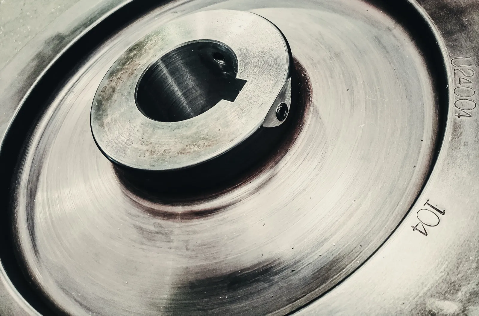
Sheaves vs. Running Wheels
A crane sheave is a grooved wheel through which a wire rope or chain passes to change direction or multiply mechanical advantage in a hoisting system. Unlike a crane running wheel, which rolls along a rail surface and bears load through its tread, a sheave contacts only the wire rope in its groove — the groove profile, groove depth, and groove hardness are the critical dimensions rather than tread width or flange geometry.
Groove wear is the primary failure mode for crane sheaves. As the wire rope passes repeatedly through the groove under tension and changes direction at each sheave, the rope and groove surface abrade each other. Proper groove geometry — matching the rope diameter with the correct groove radius — ensures the rope is supported across its full cross-section rather than contacting only the groove edges, which would accelerate both rope and sheave wear. Groove hardness affects wear rate: a sheave that is too hard will accelerate rope wear; one that is too soft will itself wear rapidly. The industry target is a sheave hardness slightly below the hardness of the wire rope's outer wires.
UTEC Industrial machines sheave groove profiles to drawing specifications, including the groove radius relative to rope diameter, tread depth (the amount of material below the groove bottom), and any special features such as fleet angle compensation on multi-layer drum applications. The reverse engineering process for worn sheaves is similar to crane wheels: send UTEC photos and measurements — no need to ship the part — and UTEC reconstructs the groove profile from close-up photos of the unworn sections near the flanges, produces a drawing, and manufactures the replacement.
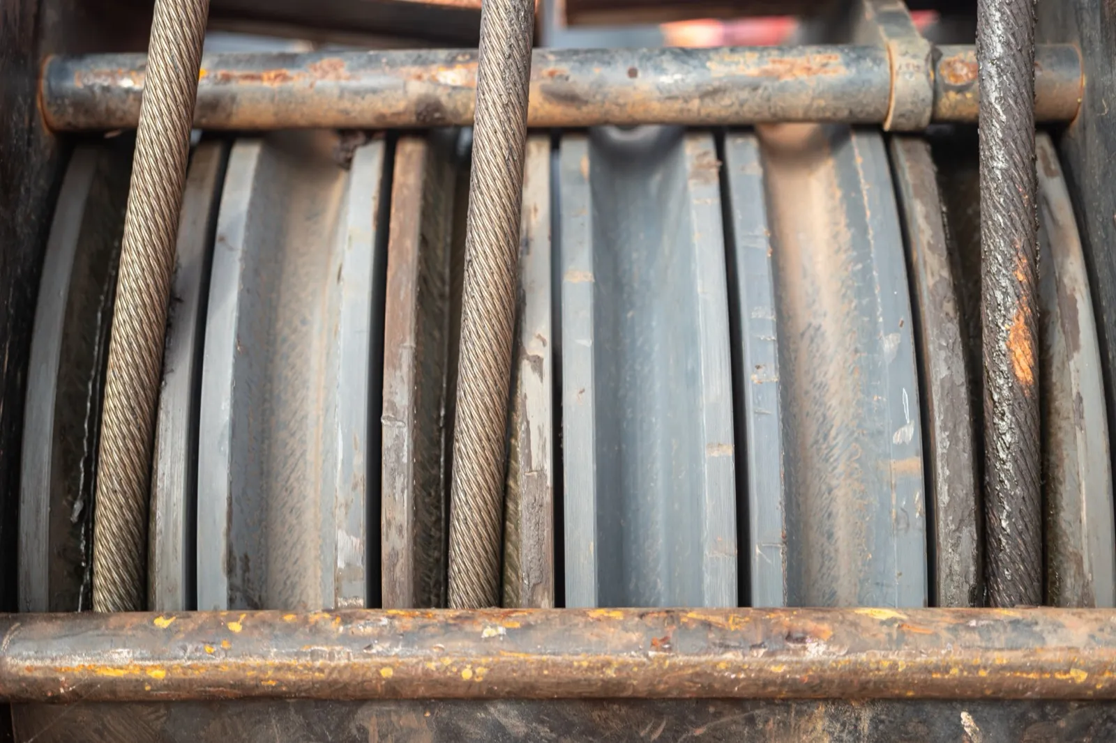
Groove Profile and Hardness Specification
Groove Profile Must Match Wire Rope Diameter
The groove radius should be 6–8% larger than the nominal wire rope radius — this provides full bedding of the rope in the groove without pinching or edge loading. Too tight a groove constricts the rope and accelerates rope wear; too wide a groove concentrates load on the center strands. Always specify the groove profile relative to the wire rope diameter on the sheave drawing. UTEC machines grooves to the tolerances stated on the drawing.
Hardness Guidance
| Application | Typical Hardness | Notes |
|---|---|---|
| Standard crane hoisting | 321–375 BHN (34–40 HRC) | Softer than running wheels; protects wire rope |
| High-cycle hoist service | 340–375 BHN (36–40 HRC) | Upper range for extended groove life |
| Hydroelectric gate hoist | To drawing; often 300–340 BHN | Low cycle rate — groove life less critical than rope compatibility |
| Heavy-lift reeving blocks | 350–400 BHN (37–43 HRC) | Higher hardness where groove wear rate is dominant failure mode |
| Customer specified | Any achievable value | UTEC hardens in-house to specified Rockwell value |
Where UTEC Sheaves Are Used
Overhead Crane Hoisting Systems
Sheave blocks in overhead crane hoist drums — both the hook block and the upper (headroom) block. UTEC machines to the dimensional specification of the existing sheave or the drawing, including shaft bore, overall width, and groove profile.
Hydroelectric Gate Hoists
Dam gate and penstock hoist systems use large-diameter, low-cycle sheaves that must maintain groove geometry over decades of service. UTEC produces replacement sheaves for hydroelectric applications from worn samples when original documentation is unavailable — common on older installations. See the Hydroelectric industry guide at the resource center.
Reeving Blocks and Multi-Part Lines
Multi-sheave reeving blocks for heavy lift require matched groove profiles across all sheaves in the block. UTEC can supply complete sheave sets for a reeving block assembly with matched dimensions, ensuring consistent rope behavior across all sheaves in the system.
Sheave Capabilities
| Parameter | UTEC Capability |
|---|---|
| Alloy Grade | AISI (American Iron and Steel Institute) 4140 (standard), 4340 (severe duty or large diameter) |
| Sheave Diameter | 6-inch to 48-inch |
| Groove Profile | To wire rope diameter and drawing specification |
| Groove Angle | Standard and custom — to drawing |
| Hardness Range | 300–420 BHN (31–45 HRC); softer ranges available to specification |
| Bore Types | Press-fit, keyed, bearing assembly |
| Custom Features | Fleet angle compensation, multi-groove profiles, flanged rim — to drawing |
| Reverse Engineering | From worn samples — groove profile reconstructed from unworn sections |
| Documentation | Raw material chemistry, hardness reports, dimensional inspection |
Frequently Asked Questions
What is the difference between a crane wheel and a sheave?
A crane running wheel rolls along a rail surface to support and move the crane structure. Its critical dimensions are tread diameter, tread width, flange geometry, and bore. A crane sheave is a grooved pulley through which a wire rope passes; it does not roll along a rail but rotates about a fixed shaft, redirecting the rope and multiplying force in a reeving system. The critical dimensions are the groove profile (radius, depth, width), shaft bore, and overall width. Both are machined from alloy steel billet and induction hardened in-house at UTEC; the specifications and design intent are different.
How is a sheave groove profile specified?
The groove profile is specified by: (1) groove radius — typically 6–8% larger than the nominal wire rope radius; (2) groove depth — usually 1.5× the rope radius to ensure adequate rope bedding; (3) groove angle (the included angle of the groove walls) for the type of groove (circular, trapezoidal, or otherwise); and (4) any special features like fleet angle or rope lead adjustments. These dimensions should appear on the drawing. If you are specifying a sheave to match an existing wire rope, provide the rope manufacturer's nominal diameter and the sheave drawing; UTEC will confirm that the groove geometry is compatible. If the existing sheave is worn and no drawing is available, UTEC measures the groove geometry from the unworn sections and produces a drawing for approval.
Should sheave hardness be higher or lower than the wire rope outer wire hardness?
Sheave hardness should be lower than the hardness of the wire rope's outer wires — the sheave is intended to be the sacrificial element in the contact pair, wearing in preference to the wire rope, which is more expensive and difficult to replace. In practice, for general industrial crane hoisting with standard 6×19 or 6×37 wire rope, a sheave hardness of 321–375 BHN (34–40 HRC) is appropriate. Higher sheave hardness than the rope's outer wires accelerates rope wear and can cause rapid fatigue of the rope's outer strands at the sheave contact point. If the sheave is significantly softer than the rope (below 280 BHN), groove wear becomes the life-limiting factor and replacement intervals shorten. The balance point between groove life and rope life is typically at 321–370 BHN for standard wire rope grades.
Can UTEC reverse-engineer a worn sheave from a sample?
Yes — the reverse engineering process for sheaves is the same as for crane wheels. Send UTEC photos and measurements — no need to ship the part. UTEC reconstructs all critical dimensions from submitted documentation — bore, overall width, flange OD, and groove profile from close-up photos of the unworn sections near the flanges, which typically retain the original profile even when the groove bottom is worn. A dimensioned drawing is produced and sent for customer approval before manufacturing.
Technical Resources
Request a Sheave Quote
Send UTEC your drawing, wire rope diameter, and groove profile specification — or send photos and measurements of a worn sheave for remote reverse engineering. We respond within one business day.
Get a QuoteLast updated: